|
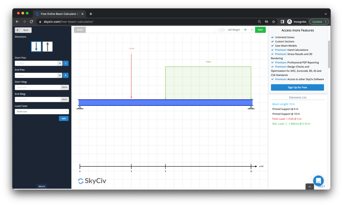
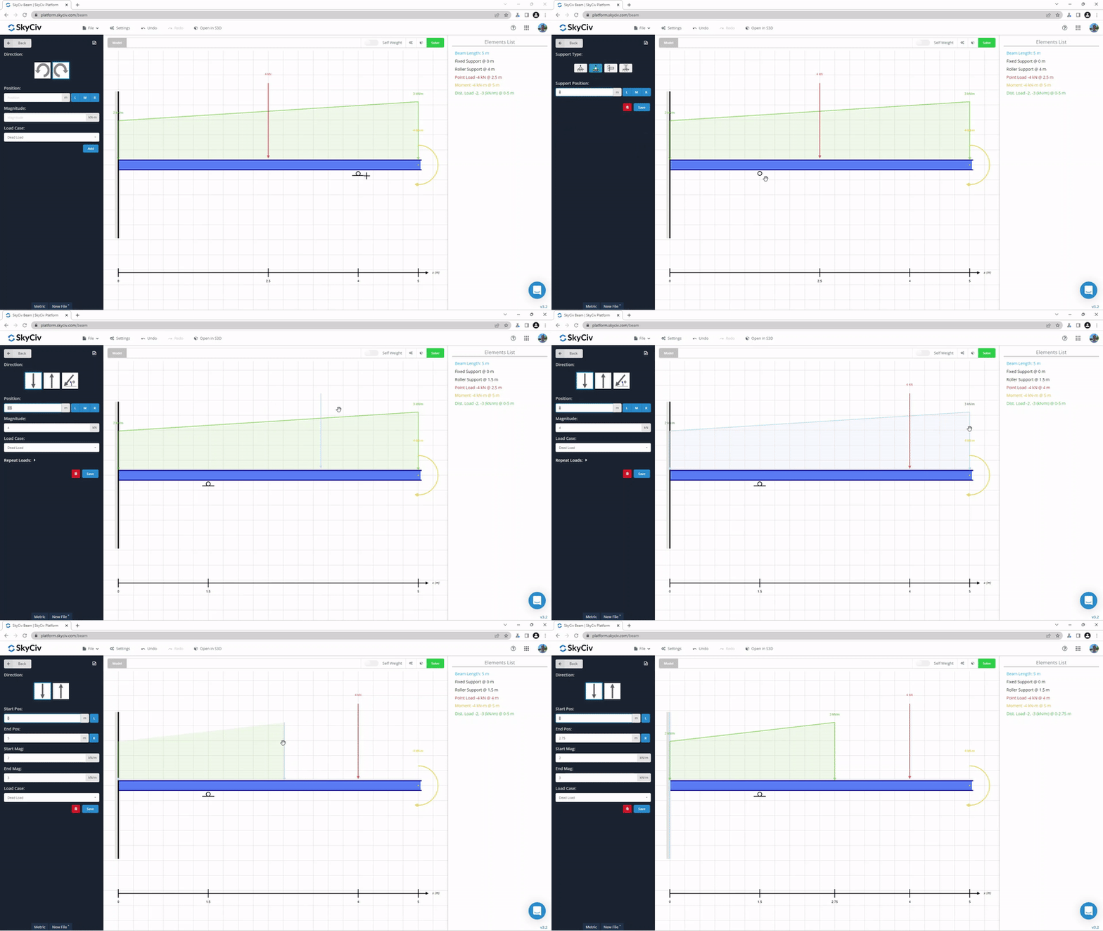
SkyCiv is a cloud-based structural engineering software and API technology provider. The company’s Free Beam Calculator is one of its most popular free resources among structural engineering students and professionals. It’s a web-based tool that allows users to perform structural analysis and design calculations for simple and cantilever beams. The free tool calculates bending moments, shear forces, deflections, and reactions for a given beam geometry and loading conditions, helping students and professional engineers design safe and efficient structures. The best thing is that it is completely free to use and accessible through your web browser. Latest update of SkyCiv Free Beam CalculatorRecently, SkyCiv has rolled out an updated version of the Free Beam Calculator with improvements in UI, promising an even better user experience. It is now mobile-friendly, allowing users to easily analyse and calculate beams directly from their phones. With a fresh new interface, this free beam tool has never been easier to use! The free beam calculator also has some new features to make it easier for users to calculate bending moment and shear force diagrams in seconds. For instance, users can now click and drag to move loads: This along with a wide range of shorthand inputs, such as comma separated input, mathematical expressions and keyboard shortcuts now make complex input a thing of the past! SkyCiv Free Beam Calculator FeaturesThe SkyCiv Free Beam Calculator is a powerful tool for engineers, contractors, and anyone who needs to perform beam calculations. The calculator is able to generate reactions, Shear Force Diagrams (SFD), Bending Moment Diagrams (BMD), deflection, and stress calculations for a cantilever or simply supported beam. The calculator guides users through a professional beam calculation workflow, allowing them to view and determine if their calculations comply with regional design codes. Beam Reaction CalculatorThe calculator also features a beam reaction calculator, which easily calculates reactions at supports for both cantilever and simple beams. The calculator includes reactions for cantilever beams, including bending moment reactions and x,y reaction forces. The reactions at supports are useful in determining the total force applied to the structure. Bending Moment and Shear Force CalculatorAnother key feature of the SkyCiv Free Beam Calculator is the bending moment and shear force calculator. This versatile structural engineering tool is used to calculate the bending moment in aluminum, wood, or steel beams. It can also be used as a beam load capacity calculator, calculating bending stress or shear stress. The calculator is able to accommodate up to 2 different concentrated point loads, 2 distributed loads, and 2 moments, which can be arranged as uniformly distributed loads (UDL), triangular distributed loads, or trapezoidal distributed loads. The calculator can account for most common beam analysis situations, as all loads and moments can be of both upward or downward direction in magnitude. Beam Deflection CalculatorLastly, the SkyCiv Free Beam Calculator also features a beam deflection calculator (or beam displacement calculator). This function allows users to observe the calculated deflection of a simply supported beam or of a cantilever beam. The calculator can also add section shapes and materials, making it useful as a wood beam calculator or as a steel beam calculator for lvl beam or i-beam design. This functionality is currently only available in the SkyCiv Beam software, which offers even more functionality for timber, concrete, and steel beam design. Check out the latest SkyCiv Free Beam Calculator now - the best free online beam tool to calculate the moment, shear, and deflection of beams. If you’re eyeing on getting SkyCiv software, this is the perfect place to get a taste of what SkyCiv Beam can offer! About SkyCivSkyCiv offers a wide range of cloud-based Structural Analysis and Design Software for engineers. As a constantly evolving company, SkyCiv is committed to innovating and challenging existing workflows to save engineers time in their work processes and designs.
Source: SkyCiv Beam Calculator
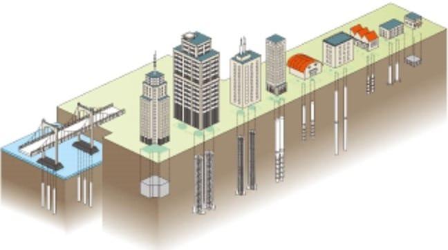
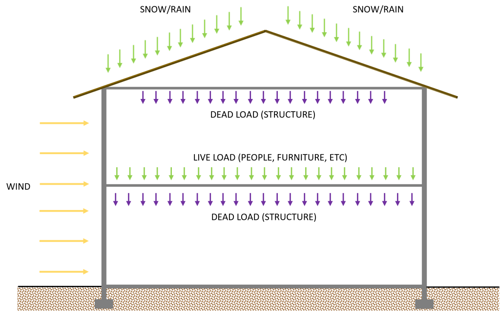
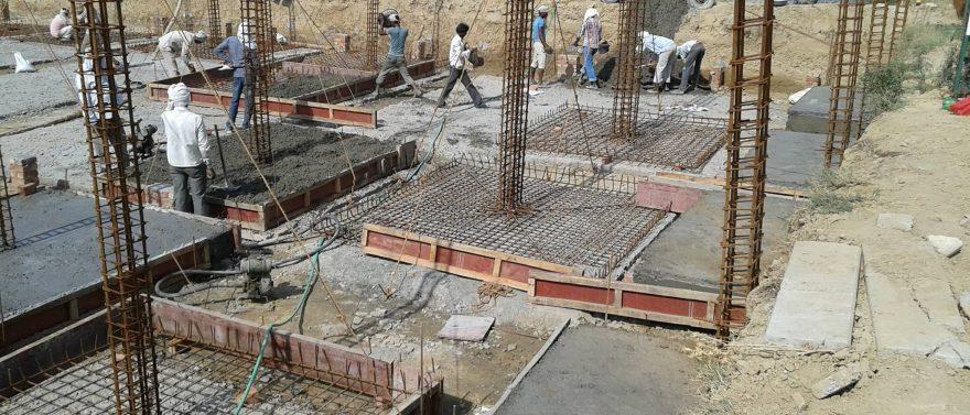
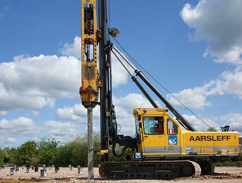
The primary purpose of a foundation in structures is to distribute the loads acting on the structure and its weight safely to the ground. Whether the structure is a residential or commercial building, a skyscraper, or any superstructure, selecting the most suitable and favourable foundation design is vital for the overall safety and economical design. Although most structural engineers would opt for a shallow foundation type as they are cheaper and have ease of construction over a deep foundation type, multiple factors may influence the selection process. (Source: philosophyofcivilenginnering.wordpress.com) Choosing the correct type of foundation for the structure is vital in ensuring overall integrity. Qualified and experienced engineers need to verify the design of the foundation and supervise the construction to assure the quality of the structure and safety of the workers. There are various types of foundations, sizes, geographical and geotechnical scenarios but here are some of the essential factors to consider by the structural engineers: Load From the StructureOne of the main factors to consider in foundation design is the design loadings of the structure. These loads include dead loads (permanent loads including the weight of the structure) and live loads (imposed loads which may vary over time). Other loads, such as the wind, seismic, snow, and rain loads, may also be considered depending on the structure's location The materials used in the construction (concrete, reinforcing bars, steel, bricks, timber, etc.), the type of structure, and the number of floors significantly affect the quantity of loads on the structure. For instance, as the number of floors increases, the structure gets heavier, and the imposed loads also increase; thus, a substantial foundation is required. Estimating the settlement of the foundation, which is also related to loads of the structure, also influences the foundation selection. Generally, low-rise structures favour shallow foundation types, while high-rise and heavily loaded structures require stronger or deeper foundations. But still, there are more factors we need to consider selecting the proper foundation design. Site LocationAdjacent buildings of the structure, the existence of any bodies of water nearby, uneven ground or slopes, and geotechnical characteristics of the ground are also important factors influencing the choice of foundation design. Foundations of the neighboring building must be considered, especially when the surrounding structures are high-rise or old buildings. It is of utmost importance to protect the foundation of the nearby structures during excavation or construction of your chosen foundation type. For structures near rivers, lakes, or sloped ground, water table level must be accounted in the design, and special excavation protection must be practiced during the excavation. Previous use of the site or nearby areas must also be identified. Determine whether the structures were used as residential, commercial, industrial, or mining. This can determine if there are any obstructions, ground contaminations, or if it is safe to excavate the ground. Soil Bearing CapacityThe bearing capacity is the capacity of the soil to support loads that are applied from the structure to the ground. It is the maximum average pressure between the foundation and the supporting soil without producing shear failure and excessive settlement. Perhaps this is the most crucial factor to consider, as this usually dictates which foundation to use. Geotechnical engineers provide the bearing capacity of the soil, ground conditions, and other soil properties from their geotechnical report. They can recommend which foundation type can be used based on the loads from the structure. Typically, soil bearing pressure of 100kN/m2 or higher is adequate to support structures up to 4 stories high using shallow foundations, such as concrete footing. Higher structures can consider using raft foundations or deep foundation types. For concrete footing calculations, you may try SkyCiv’s Concrete Footing Calculator for free! Ease of ConstructionWhether shallow or deep foundations, every foundation type requires different intensities of labor, skillsets, equipment, and duration. The construction of a deep foundation is usually more complex and costly than shallow foundations. They require heavier equipment for logistics, boring and driving piles, and bigger storage. Proper construction and time management are necessary to identify and avoid potential problems and delays in constructing the foundation. The images below show the difference between the construction of concrete footing and precast piles. (Source: facebook.com/CivilWork) (Source: aarsleff.co.uk) Economic DesignWith all the factors mentioned above, engineers may still come up with more than one suitable foundation, or the selected foundation is beyond the project's budget. The cost of each foundation type varies in terms of how they are constructed, materials, the number of labourers, equipment, and duration. In this case, the structural engineer may design the cheapest foundation without compromising the durability, quality, strength, and safety of both the structure and the workers.
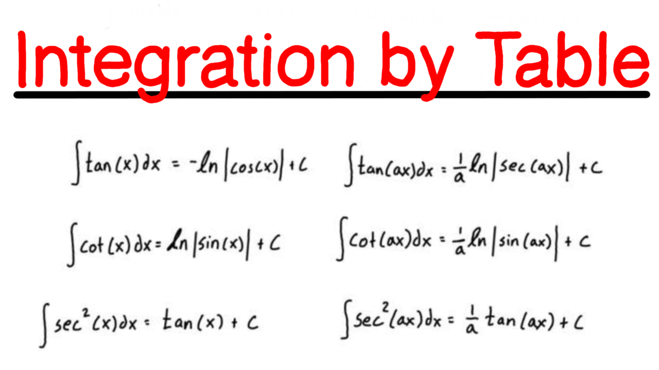
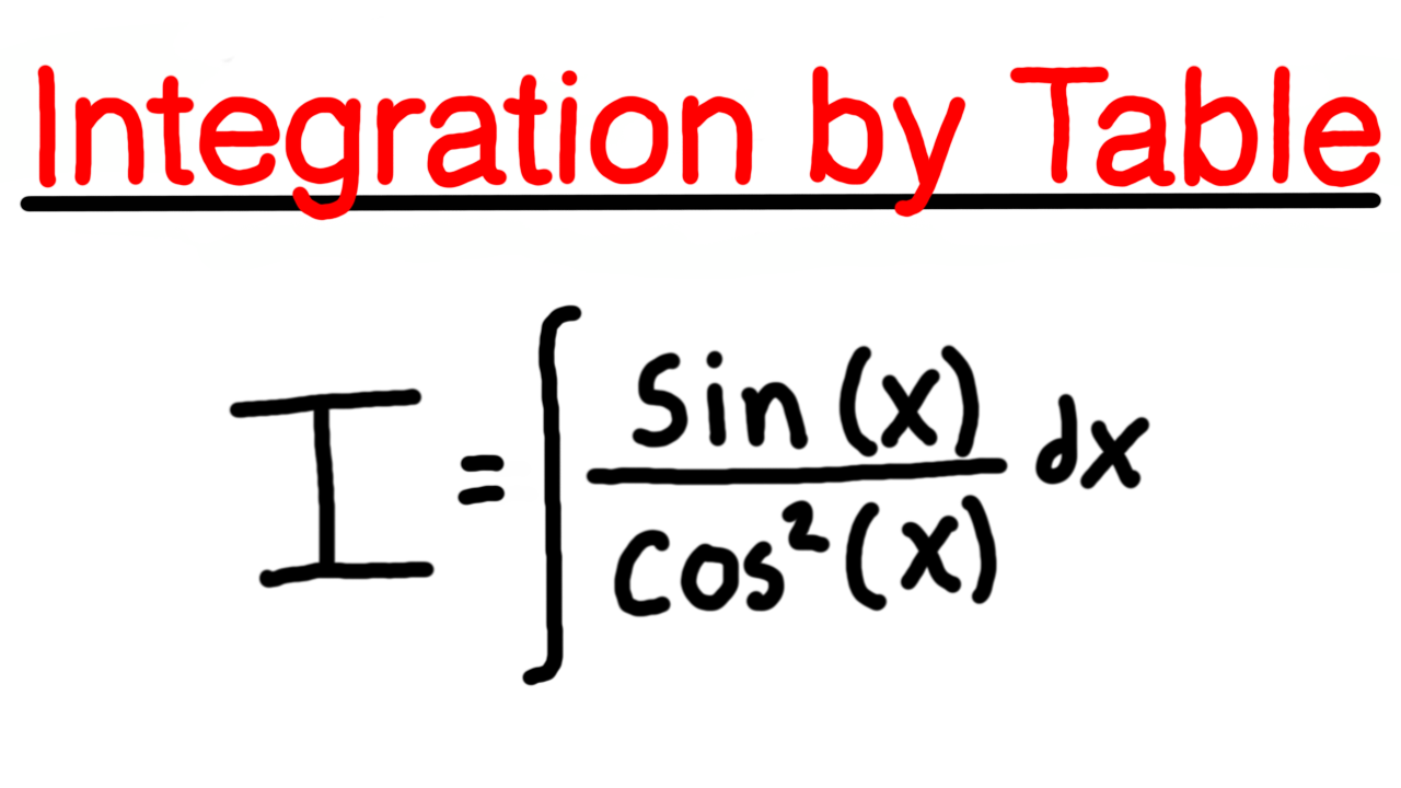
Here are four tutorials and 9 fully solved practice problems that introduce and explain the concept of integration by table. This is the most basic form of "integration" and is what many more advanced calculus problems will eventually reduce to.
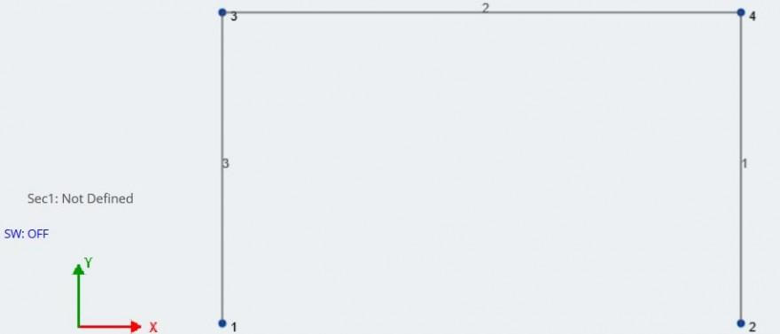
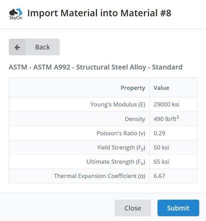
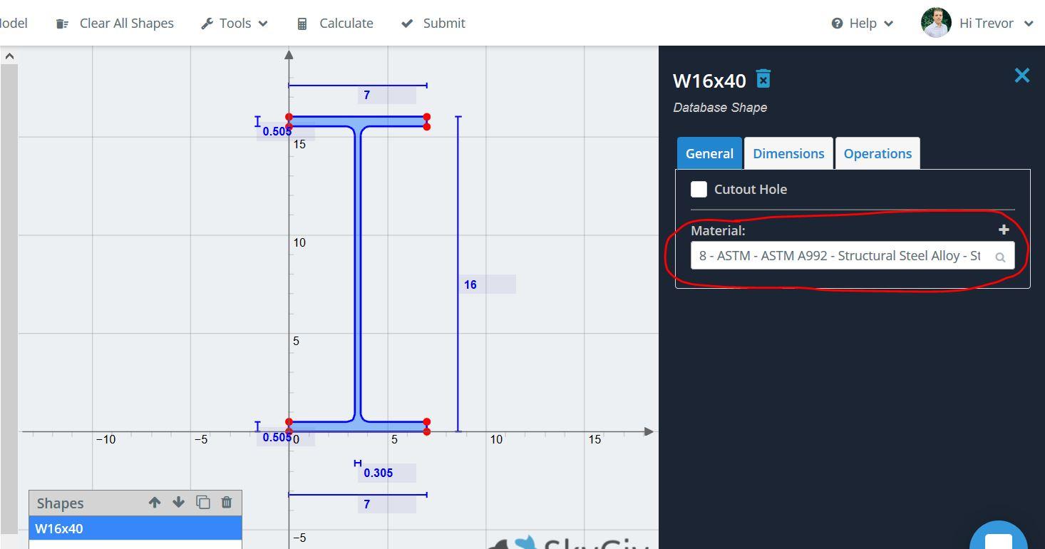
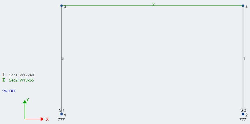
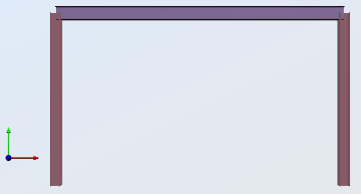
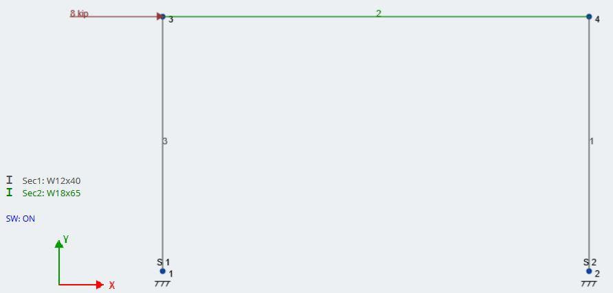
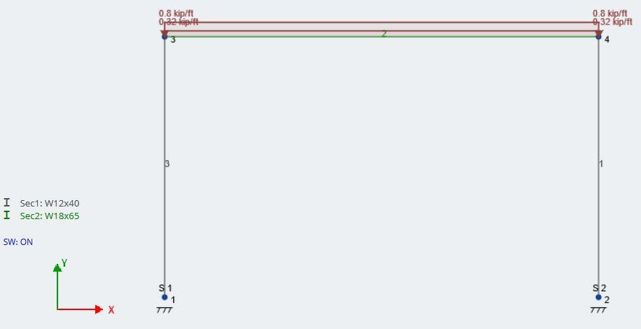
How to model, analyse and design a Steel Moment Frame as per AISC 360 and structural analysis softwareMoment frames are combinations of columns and beams connected with partially or fully restrained connections. Moment connections are very important types of frame connections and cannot be considered simply supported conditions. They are used in similarity to shear walls and braced frames; they resist lateral forces in conjuncture with vertical forces. Because of the fixed nature, frame members’ rigidity is the main source for the lateral stiffness of the frame. Braced frames are usually a cheaper option based on required material, but moment frames give architects and designers more space between columns and therefore give a better aesthetic. Modelling and Analyzing a Moment FrameModelling For modelling, we will be using SkyCiv’s steel design software (get started for free at skyciv.com). But before we get into modelling, make sure to confirm what units you are working in. This can be done by going to Settings on the top right of the toolbar. For this example, we will be operating with Imperial units. We will assume our single bay moment frame has a centroid beam height of 18 feet and a 30 foot span. Also, we will assume our moment frame is made up entirely of W-shapes from the AISC database and are fabricated from ASTM A992 Gr. 50 steel. Lastly, the trial column and beam size of W12x40 and W18x65 will be used, respectively, To start the workflow, lets input the nodes of our moment frame. Go to Nodes on the input tab (left hand side of the screen). The nodes of our frame will be (X,Y): (0,0), (30,0), (0,18), and (30,18). Now let’s generate the two columns and beam that make up our frame. To do this, there are two options: 1) go to Members in the input tab and type in the end nodes for each of our members or 2) draw the members in using the Pen Tool located on the right vertical toolbar in the model space. Because we are working with a moment frame, the end releases of each member at each connection location needs to be fully fixed, denoted as “FFFFFF” and highlighted as “Frame” when creating members within the Members tab. Take a look at our moment frame so far: Notice, “Sec1” is the section applied to our current members and is “Not Defined” because we have not applied a section yet. Before we assign sections to the members, lets import the correct steel material into our model. Go to Materials – Database in the input tab. Follow the drop downs for each relative field until we have found the correct material and see this: Click submit to import the material. After importing the wanted material, lets assign our member sizes. Go to Sections on the input tab and click on Builder. Now, are operating within the SkyCiv Section Builder module, directly integrated with our current project in S3D. While in Section Builder, lets import the two W-shapes by going to the Database portion of the section builder and selecting each shape. Before clicking Submit, make sure that the material on the right hand side is set to the desired material that we want associated with both members: ASTM A992 Steel. After bringing the two sections into the model, assign them to each member using the Section ID field on the input tab while each member is selected. For a more in-depth look at SkyCiv Section Builder and its capabilities, check out its Software Documentation. The last thing we need to do is apply a support condition. Unlike gravity columns or columns part of a braced frame, our column supports need to be fully fixed and therefore will experience moment at the base. To add supports, Ctrl + click on both nodes, right click and then left click Add Supports. Go to the input tab – it will already have the nodes selected – and select the fixed support condition. This can also be done by going to Supports in the input tab and applying the supports to each node. Our stick model should now show two different members for the columns and beam in addition to our supports: For our moment frame, we also need to make sure that the orientation of our columns is correct and favorable for lateral action. Because the moment frames will be experiencing lateral forces, the strong axis of the column is almost always perpendicular to the load direction. In this case, our lateral force will be in the X-direction, so the column flanges should be perpendicular to the X direction. A good way to verify the orientation of your members is by entering the 3D rendering. To do this, go to the right toolbar in the model space and click on the shape that looks like a 3D cube, will bring you into the 3D render of your model. Take a look at our moment frame in 3D: You can see that our columns are orientated the correct direction. With a more complicated 3D structure you can rotate the orientation of any member by selecting the member, clicking on Advanced, and then inputting the intended rotation in degrees into the Angle of Rotation field. Before you load your structure, double check that you have the correct supports, sections, and materials for each section. Loads and Load Combinations Notice, in previous figures that our self-weight was turned off, lets turn this on now. Click on the “SW: OFF” in the model space to bring up the self-weight input tab and turn it ON. SkyCiv will now take each members self-weight into account when doing the analytical calculations. For practical purposes, lets assume our moment frame is located in a building where the beams are spaced at 8 ft. Therefore, for one-way loading, our tributary width is 8 ft. For superimposed loading, lets assume that our moment frame experiences the following unfactored loads: LateralWindLoad=8kips@topelevationLateralWindLoad=8kips@topelevation DeadLoad=40psfDeadLoad=40psf 40psf∗8ft=320lb/ft=0.320k/ft40psf∗8ft=320lb/ft=0.320k/ft LiveLoad=100psfLiveLoad=100psf 100psf∗8ft=800lb/ft=0.800k/ft100psf∗8ft=800lb/ft=0.800k/ft Because our moment frame is symmetrical, we will only look at one wind direction. If the frame were to see differing magnitudes of wind load in different directions, you would need to add that wind load case as well. Let’s start with the lateral point load from wind. Go to Point Loads in the input tab on the left. We will apply the 8 kip load to Node 3 in the X-direction. Then, we are going to add a corresponding load group by typing in “Wind Load” into the Load Group field and hitting Accept. Our wind load should now look like this: Next, lets apply our superimposed dead and live loads as uniform distributed loads. Go to Distributed Loads and type in the member ID (member 2) for our beam. Then, in the Start Y-Mag and End Y-Mag, input the magnitude of 0.320 k/ft for the dead load. Similar to the wind load, type “Dead Load” in the Load Group field to generate a corresponding load group. Repeat this process for the Live Load. Here is how our model looks with both Dead and Live Loads applied: The last major step before analysis is generating the Load Combinations. SkyCiv gives users the ability to import load combinations directly from codes from countries around the world. Because we are working with Imperial units and AISC shapes, we will import our load combinations from ASCE 7-16. This will ensure that our design considers a wide range of possible loading scenarios and conditions, to ensure the structure is safe in most situations. Now that we have generated our nodes, members, supports, loads, load cases, and load combinations, we can commence our analysis. For any information about any of these steps or about using S3D, check out our Software Documentation. Analysis, Results, and Post-processing It is good practice to run a Repair Model (or similar) to repair any inconsistencies or merge nodes in your model before beginning the analysis of your structure. Also, make sure your project is stable by checking end releases and support conditions throughout. Lastly, go to Settings – Solver to look at and edit any pertinent analysis settings, such as convergence tolerance during P-delta analysis or the number of evaluation points per member. Because we did not include any dynamic loading into this example, there are three solution methods that we can use:
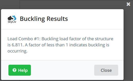
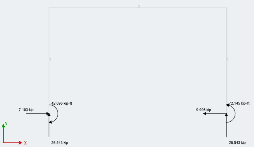
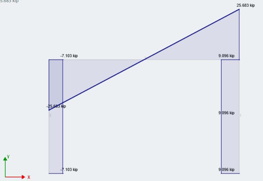
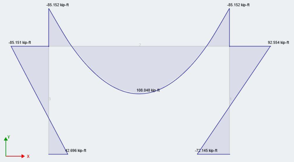
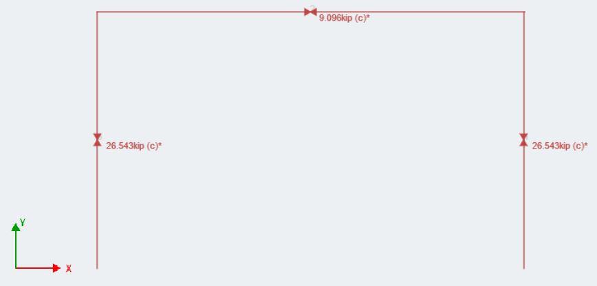
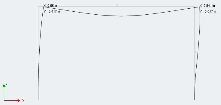
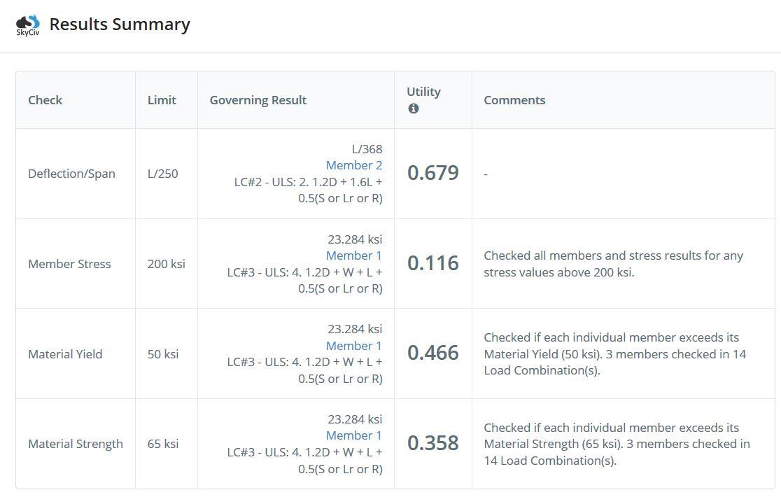
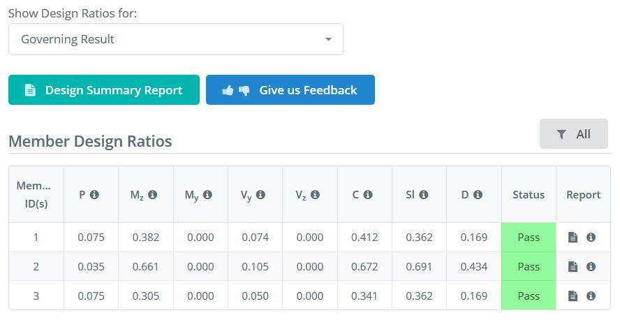
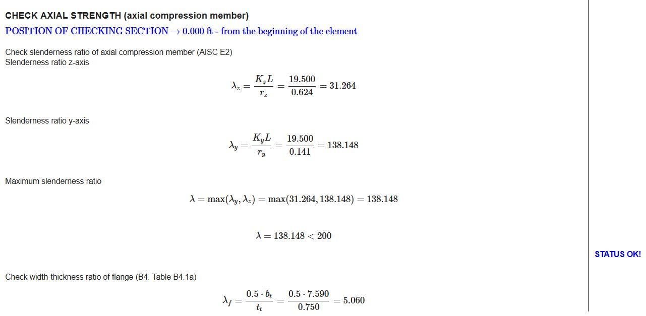
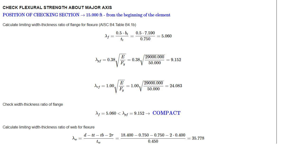
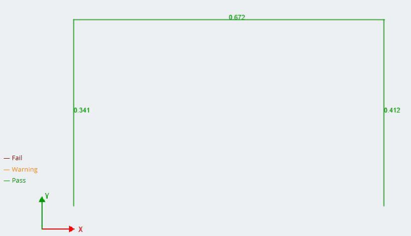
To learn more about each analysis type in SkyCiv Structural 3D, click here. At a minimum it is suggested to run the Linear Static + Buckling analysis to see if any members in your structure are subject to buckling. We will use Non-Linear Static + P-delta analysis due to the second-order effects caused by the lateral wind load. Find the analysis options on the drop-down after hovering on Solve, located on the upper toolbar. After generating the results, we found that there is no concern for buckling of our frame, thanks to the buckling analysis prompt: On the left side of the results page you can see the different types of forces and results that can be shown. Any individual load combination can be evaluated, as well as any individual load case or group. For design purposes, we will be using the Envelope Absolute Max because it will show us the worst forces that each member experiences. Note, the envelope is not showing the worst load combination, but the worst combination of all of the load combinations at once. This loading condition is not realistic, but it “envelopes” all of the possible forces that each member could see. See the figures below for the pertinent force and deflection diagrams for our moment frame: While there are no direct code requirements for story drift not due to seismic loading, it is recommended to keep story drift of structures between 1/500 and 1/200 the story height (Ellingwood). For this frame, the story height is 18 ft, so our drift should be between (18 ft/500) and (18 ft/5\200), or between 0.43 and 1.0 inches. Our envelope max drift is shown as 0.55 inches, which is actually closer to the lower limit of H/500, which satisfies our engineering judgement. The button, Results Summary, is used by the majority of our users to quickly check the stress limits of their members, especially for steel. This window gives you a snapshot of the member that is closest to its stress capacity. Users can customize stress and deflection limits for their project using the toolbar on the right side of the modelling space. Here is a glimpse of our frame using the Results Summary: The Deflection/Span and Member Stress are the customizable fields. Lastly, don’t forget that Structural 3D gives its users the ability to print reports with almost unlimited functionality and customization. One of the biggest advantages of using the SkyCiv suite is that although all of the modules can used as standalone, most of them are integrated directly and are better suited to be used directly from Structural 3D. This way, all of the analytical results we have just calculated can be pulled directly into adjunct modules for design of members and connections. Member Design: Checking and Selecting a Design our MembersWhen opening the Member Design module, your project's job details will be brought in where you can change and confirm them. The next input tab lets you customize the phi-factors for steel. We will keep the defaults as laid out by AISC. The Members input tab is a good place to stop and look at your list of design-able members. Because of SkyCiv’s integrated ecosystem, it will import all of the steel members in your 3D model and calculate unbraced lengths, effective length factor, and slenderness ratios for them. It also lists the materials and different sections present in your model. Forces gives you the option to design for any single load combination, but is defaulted to the envelope forces of your structure. You can view the absolute worst case forces for your structure for any load combination as well. Now that we have gone through the input options, lets Run Design, you should see this output: :This window is the main results page that will show you the unity, or capacity ratios, of each design check. Don’t forget to hover over the tooltips (“i” within a circle) if you are not exactly sure which each variable stands for. You can see that the Combined Forces limit state is governing for all three members. The Design Summary Report is similar to the Results Summary and Report for the analysis phase, it gives a succinct look at the forces that the members are experiencing and whether or not capacity has been reached. One of the most exclusive functions to SkyCiv design module is the individual member design reports that are available by clicking one of the report icons under the Report column for every member; this can be printed to a PDF or HTML. These reports give much more detailed hand calculations of the checks that are being done for the member. For example, lets take a look at a few snippets of our beam (Member 2): The start of the axial strength check: The start of the flexural strength check: Our governing limit states check: If you look in the modelling window, you will see that the frame shows the design ratios of each member as well as color coded. Because all three of the members “Passed”, here is what our current frame looks like: Note: any limit state’s design ratio can be displayed in the model space. It will default to the governing case for each member to give users the best possible picture of what members may need revising. For more information about the Member Design module the code versions it supports, see our Software Documentation. What’s Next? SkyCiv is always updating and adding features to our platform, with software updates almost every 2 weeks! Most other structural engineering software come out with updates only once a year. Major design updates that are currently in development at the time of this article include:
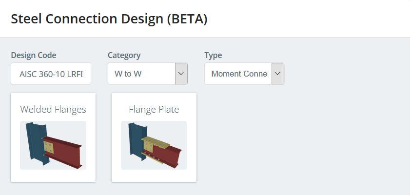
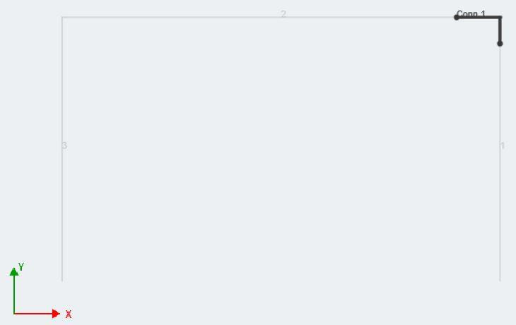
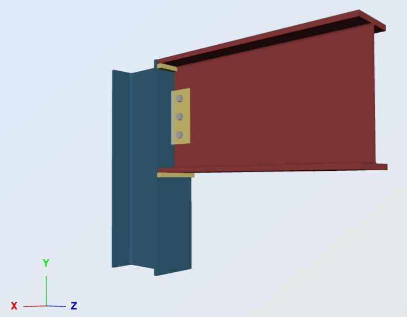
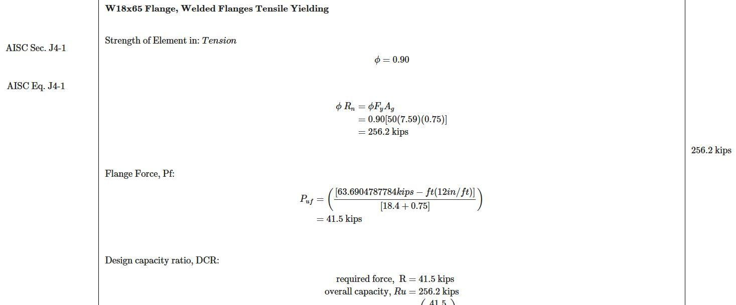
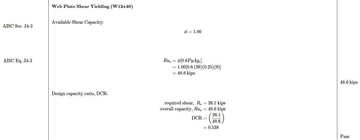
Need some other features? Request them today at [email protected] SkyCiv Connection Design: Designing a Moment ConnectionNow lets look at designing the two beam-column connections for our frame. They will both be designed as moment connections due to the presence of moment at the connection location. Make sure that the Envelope Absolute Max is shown in the analysis portion of the workflow because the connection module will bring the forces that are shown at the time you enter the module. Similar to Member Design, to enter the Connection module, click on the Design button and Change Module in the drop-down menu. Add a connection by pressing Add Connection Assembly. Toggle to Moment Connections and find the Welded Flanges moment connection type. The connection selection window should look like this: With the connection type chosen, we need to identify the parent and child member for our connection. We will be using the same connection for both beam ends to simplify the design. If we look back on our analysis, we notice that the connection on the right sees the larger moment magnitude, so we will design for this connection. In this case, the column on the right will be the parent member (member 1), and the beam will be the child member (member 2). Once this has been edited in the correct input area, the model space will identify the connection and should look like this: This gives the user a visual representation and confirmation of the specific connection location(s) they are designing for their structure. To enter the design, click on the pencil image on the input tab. Note, the connection can and will be rendered in 3D for you to look at while the inputs are being changed. Each time there is a change to the connection, click on the Render button to refresh the rendered image. Forces can be customized, but thanks to the connection module’s integration with S3D, they will be filled automatically. As aforementioned, the forces listed will be taken from whatever load combination/envelope was being viewed in the analysis portion of S3D. The Connection input tab is where the majority of editing is done. Parent Member and Child Member 1 should be accurate because the information is pulled directly from the member information inputted in S3D. Always make sure to check the pertinent design values in these areas. Go through each tab and put in the desired angle dimensions and bolt edge distances, as well as weld size. We are going to use an A36 PL1/4x4x0′-9″ with (3)-3/4″ Group A bolts. For a fillet weld size, we will start with 1/4″. Put all the required information into the relevant fields, then hit render. The 3D connection image should change and update to the most current information. Here is our example: Click on Run Design. Results for each portion of the connection should be shown on the left. Similar to the Member Design module, limit states are color coded to tell the user if their connection design is under or over capacity. Fortunately for us, the connection that we manufactured has passed each design check and will work for our frame! Following the theme of transparency and accuracy, SkyCiv Connection has the power to print full hand calculations for each steel connection in accordance with AISC 360-10 Chapter J. The limit states that are shown in the hand calculations are summarized in the results after each design is ran. For continuity, take a look at a couple of snippets from this connections report: Welded Flanges Tensile Yielding (AISC Sec. J4): Web Plate Shear Yielding (AISC Sec. J4): Lastly, when operating with the Connection module, notice that you can export the connection in a drawing format, or directly to AutoCAD. Considering the amount of time spent drafting details from scratch, this export feature has saved not only structural engineer’s time, but structural designer’s as well. For more information about the connection module or moment connections in general, see our Software Documentation. What’s Next? SkyCiv is always updating and adding features to our platform, with software updates almost every 2 weeks! Most other structural engineering software come out with updates only once a year. Major design updates that are currently in development at the time of this article include:
Foundation Design: design isolated and combined footings and piles for columns, directly integrated with your 3D model in Structural 3D Final ThoughtsWe were able to go through the design of a simple 2D moment frame from conception, all way through connection design and even detailing. Throughout this process we never had to leave the program or load multiple modules separately. Each module seamlessly leads to one another unlike any other structural engineering software available. All the while, you are operating through any browser, on any device, with all of the files being saved on the cloud. Stretch the capabilities as far as you possibly can with the SkyCiv suite! References
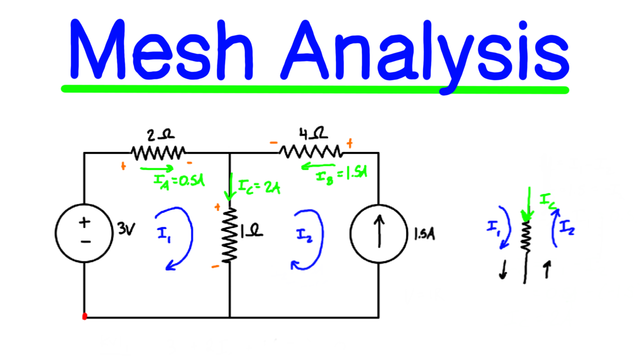
Here are five tutorials that introduce and explain mesh analysis for DC circuits. The lessons cover the basics principals of mesh analysis, along with some fully worked examples, as well as an introduction to supernode analysis, which is a special case of mesh analysis that occurs when there is a current source between two loops of the circuit.
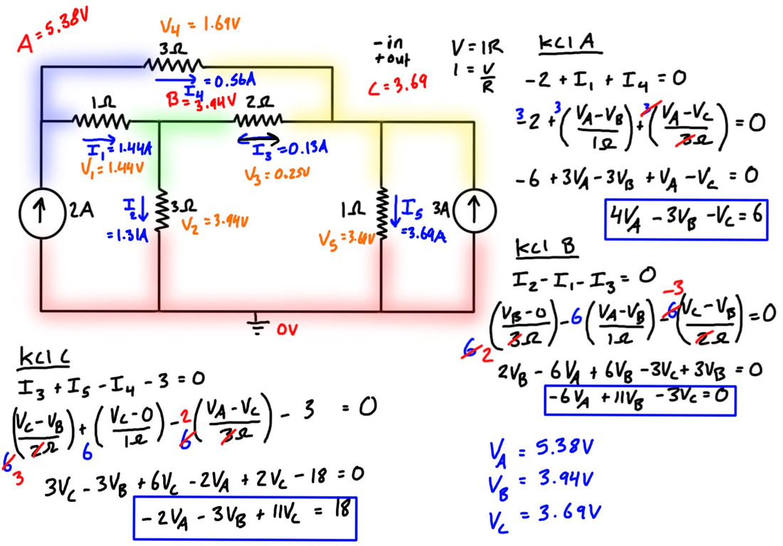
These 5 tutorials introduce and cover Nodal Analysis for circuits, and Supernode Analysis. There is a dedicated video to introduce both Nodal Analysis and Supernode Analysis, and 3 fully worked through example problems with various configurations of nodes, branches, and power sources (current sources and voltage sources). Generally, if you follow the steps laid out in these lessons, you'll be solving these problems like a boss! These tutorials are part of a full Circuit Analysis Course.
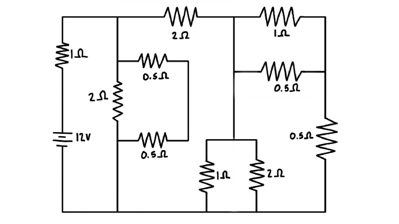
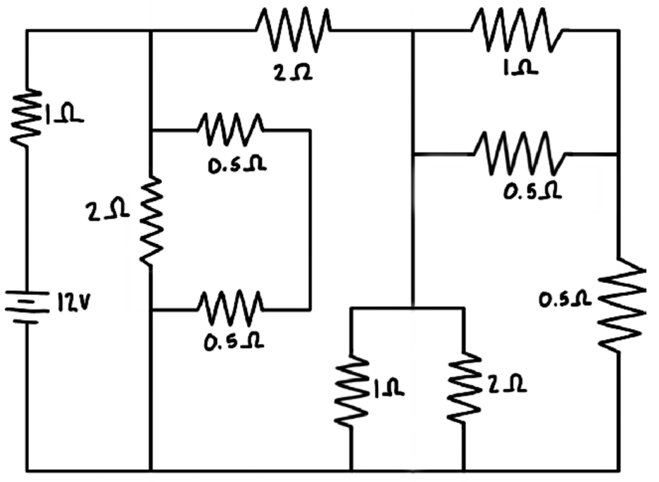
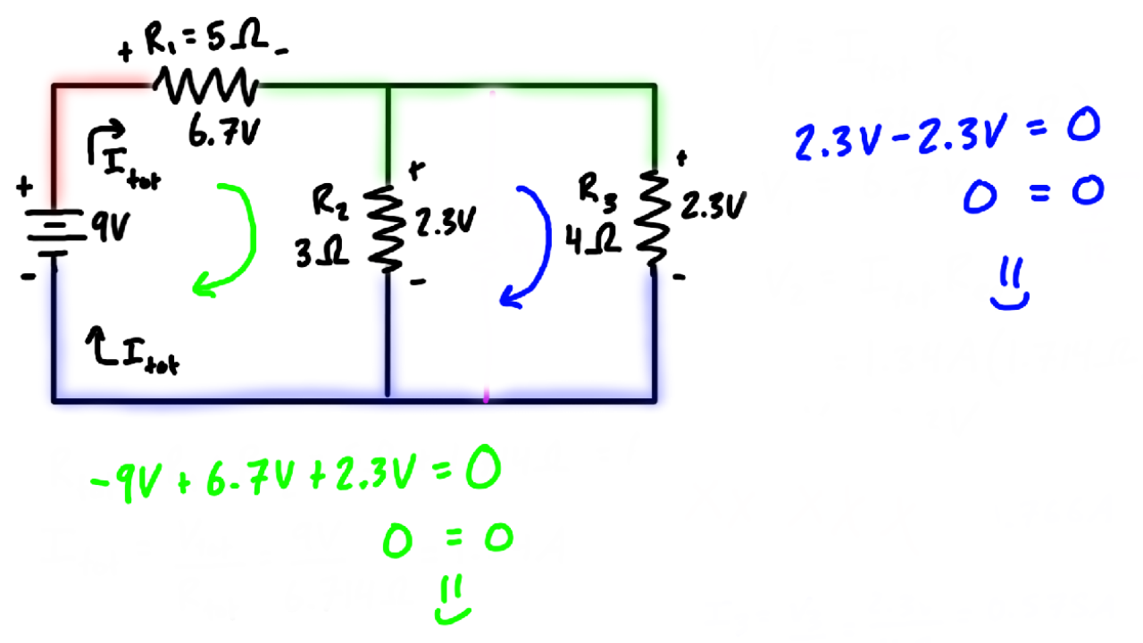
Here are 7 tutorials that cover Series and Parallel Resistors. In the lessons, I go over how voltage division and current division work, and a few examples of each. I also run through a more complicated example that involves both voltage division and current division, but you'll see in the end that it's actually pretty straightforward to combine the two when seeking the equivalent resistance of a circuit. The full circuits course can be found here. Here are 9 new video tutorials that cover Ohm's Law, Kirchhoff's Laws. They introduce the concepts and also go over a few worked examples of varying difficulty.
The rest of the Circuit Analysis course can be found here. |
|
© Copyright www.engineer4free.com 2012 - 2024 All Rights Reserved
About | Course List | Patreon | Newsletter | Blog | ToS | Contact Engineer4Free is committed to sustainability. You should be too. |
|


 RSS Feed